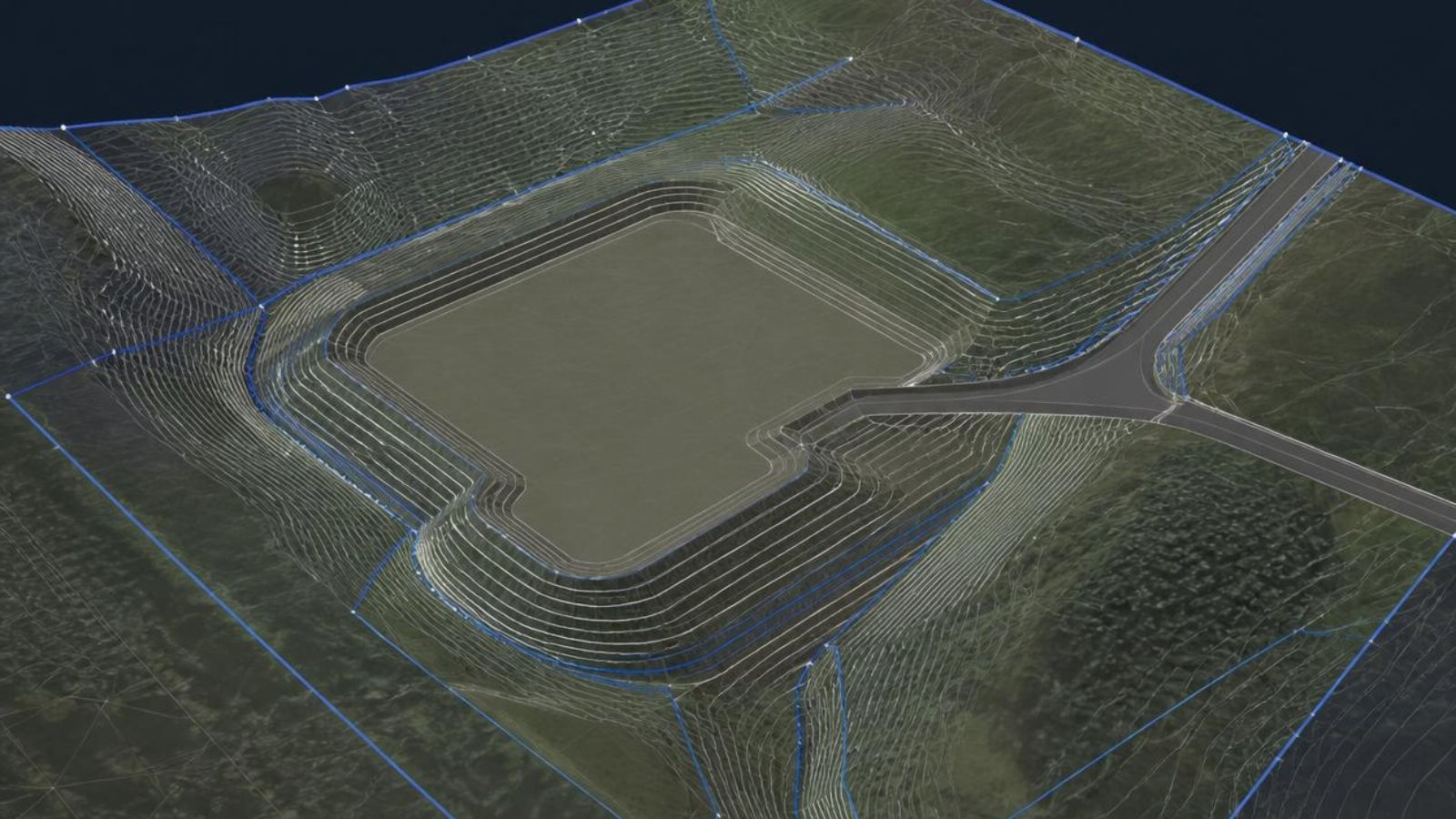
Grading can look deceptively simple. Draw some lines, assign some elevations, build a surface and make the contours look right.
In practice, good grading requires much more than producing geometry that looks correct on a plan. It needs to respond to regulatory requirements, existing site conditions, drainage, access, constructability and the overall objectives of the project.
Just as importantly, the model needs to be useful to the people who will work with it after it leaves the designer's desk: engineers, surveyors, contractors and other members of the project team.
My approach is to treat the Civil 3D model as more than a drawing. It should be a structured representation of the design that can be reviewed, tested, communicated, staked and ultimately constructed.
1. Establish the Governing Requirements
Before building grading geometry, I want to understand what the site is required to accomplish and what requirements govern the solution.
Depending on the project, that can include:
- Municipal bylaws and zoning requirements
- Development permit conditions
- Subdivision requirements
- Provincial standards
- Accessibility requirements
- Drainage and stormwater requirements
- Road and access standards
- Project-specific engineering requirements
Understanding these constraints early helps prevent a common problem: developing a grading concept that looks good geometrically but does not actually satisfy the project requirements.
2. Understand the Survey Data Before Building the Surface
A surface is only as useful as the information used to create it. Before building an existing ground surface, I review the survey data itself rather than immediately accepting the resulting surface as fact.
Things I look for include:
- Coordinate system and units
- Horizontal and vertical datums
- Survey control and benchmarks
- Survey monuments and property corners
- Legal survey boundaries and surveyed limits
- Spot elevations
- Breaklines
- Contours
- Feature codes and descriptions
- Existing infrastructure and utilities
- Structures and site features
- Topographic coverage and potential gaps
Legal survey boundaries are particularly important. The survey establishes the surveyed limits and legal information; Civil 3D provides the tools to represent and use that information within the project model.
I also review how the surface behaves. A surface can successfully build and display contours while still containing gaps, questionable triangulation or areas that do not accurately represent the actual site.
3. Identify the Controlling Elevations and Geometry
Not every elevation on a site carries the same importance. Some features control the design, while others simply describe existing conditions.
Typical controlling information can include:
- Road elevations and road connections
- Building finished floor elevations
- Entrance and accessibility elevations
- Property boundaries
- Drainage infrastructure
- Outlet elevations
- Adjacent property elevations
- Utility connection elevations
- Utility inverts and rims
- Retaining walls
- Curbs, ditches and culverts
- Critical tie-in elevations
I want to understand which geometry actually controls the design and which geometry is simply representative or reference information.
That distinction becomes important when developing feature lines, grading objects and proposed surfaces.
4. Understand Where the Water Needs to Go
Grading and drainage are closely connected. A grading model should make it possible to understand how water is expected to move across the site.
I look at existing flow paths, proposed drainage routes, low points, outlets, swales, ditches and the interaction between grading and drainage infrastructure.
I also consider whether the proposed grading creates trapped water or redirects water in a way that could affect adjacent properties or existing infrastructure.
5. Develop the Grading Geometry
Once the controlling information is understood, I begin developing the proposed grading geometry.
Depending on the project, that can involve feature lines, grading objects, alignments, profiles, corridors, breaklines, proposed surfaces, surface edits and spot elevations.
The important part is selecting the appropriate tool for the problem rather than creating unnecessary geometry simply because Civil 3D allows it.
I want the model to communicate design intent and make the controlling geometry clear.
6. Build With the Field and Downstream Workflow in Mind
A grading model eventually leaves the computer. Surveyors may use it for layout. Contractors may use the surface for machine control or construction layout. Designers may extract points, feature lines, alignments or profiles from it.
That means the model needs to contain usable information, not simply geometry that looks good on a plan.
A line drawn on a plan without the appropriate elevation or feature-line structure may have very little value to the person trying to stake it in the field.
The overall workflow can be thought of as:
Each stage depends on the information produced by the previous one.
7. Use the Model to Evaluate Options
One of the major advantages of working in Civil 3D is that the model can be used to evaluate the design rather than simply document it.
I can test different building elevations, road connections, drainage routes, slopes, grading concepts and earthwork scenarios.
This can reveal problems early and provide useful information when comparing potential solutions.
8. Check the Model in More Than One Way
I don't rely on contours alone to determine whether a grading model is correct.
Depending on the project, I may review:
- Contours
- Spot elevations
- Slope and elevation analysis
- Profiles
- Cross-sections
- TIN behaviour
- Drainage paths
- Cut and fill
- Feature-line elevations
- Design criteria
- Surface boundaries and breaklines
I also consider how the surface will behave if its source information changes. Organized source data, breaklines, boundaries and surface definitions make future revisions much easier to manage.
9. Consider Constructability
A mathematically correct grading solution can still be awkward to construct.
I consider transitions, tie-ins, access, equipment, cut and fill, retaining requirements, drainage, slopes, existing features and how the design will actually be laid out in the field.
The goal isn't simply to create a technically correct model. The design intent needs to be understandable and practical to build.
10. Complete QA/QC
Before considering a grading model complete, I review the model and supporting information as a whole.
That can include checking:
- Surface boundaries and breaklines
- Critical elevations and slopes
- Contours and surface behaviour
- Profiles and sections
- Drainage and tie-ins
- Feature-line elevations
- COGO point information
- Coordinate systems and units
- Surface naming and organization
- Layers and drafting standards
- Legal survey information
- Deliverable formats
- Downstream data requirements
The objective is to make sure the model, drawings and supporting information all tell the same story — and that the next person in the workflow can actually use the data.
The Bigger Picture
Grading is ultimately a balance between constraints. Existing conditions, regulations, drainage, access, structures, property boundaries, constructability and project objectives all have to work together.
Civil 3D is very good at representing those relationships, but the software doesn't determine the right solution. That still requires engineering judgement, technical understanding and careful interpretation of the available information.
A well-built model provides a common source of information for understanding existing and proposed conditions, testing alternatives, identifying problems and communicating decisions.
The drawing is one of the outputs. The model is the tool that helps get you there.
About Pollard CAD
Pollard CAD provides Civil 3D modelling, grading, surface development, infrastructure drafting, survey data processing and technical drafting support to engineering, surveying, municipal, development, construction and industrial clients.
With more than 15 years of civil engineering project experience, my focus is on producing practical, structured models that are useful beyond the drawing itself.
Build the model right, understand what it is telling you, and make the information useful.